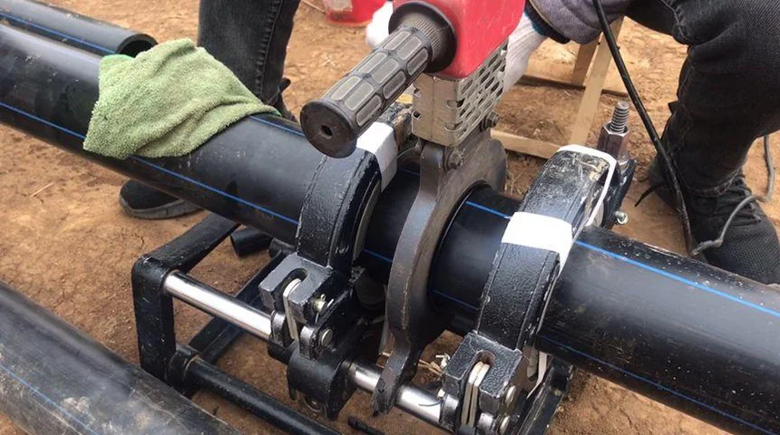

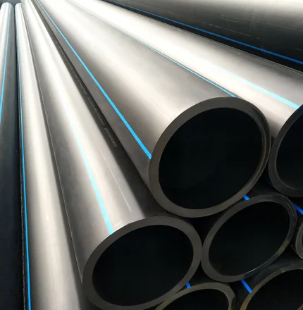
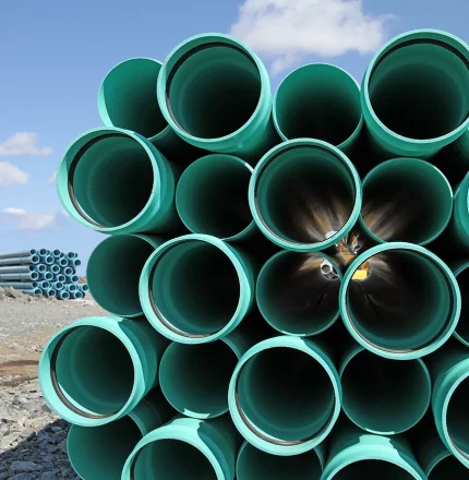
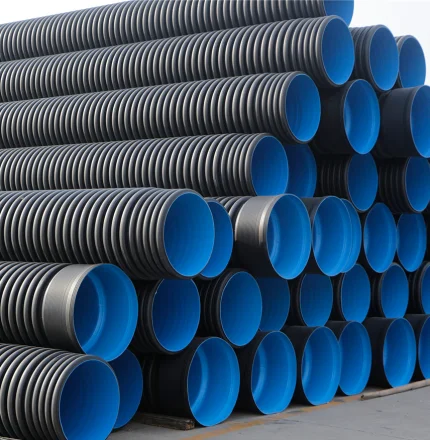
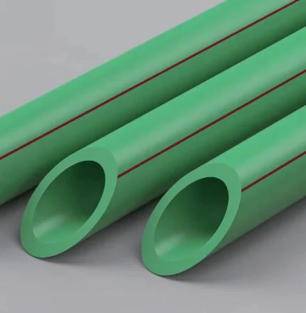
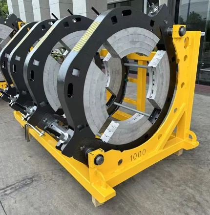
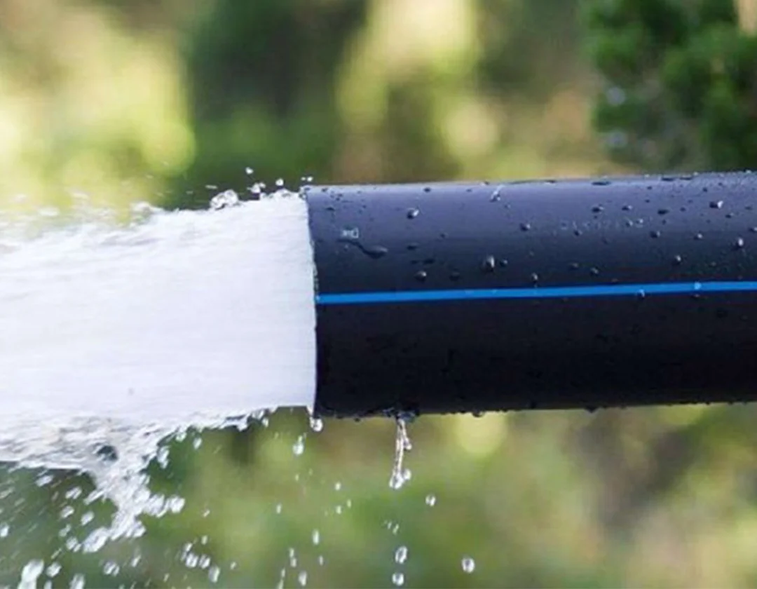
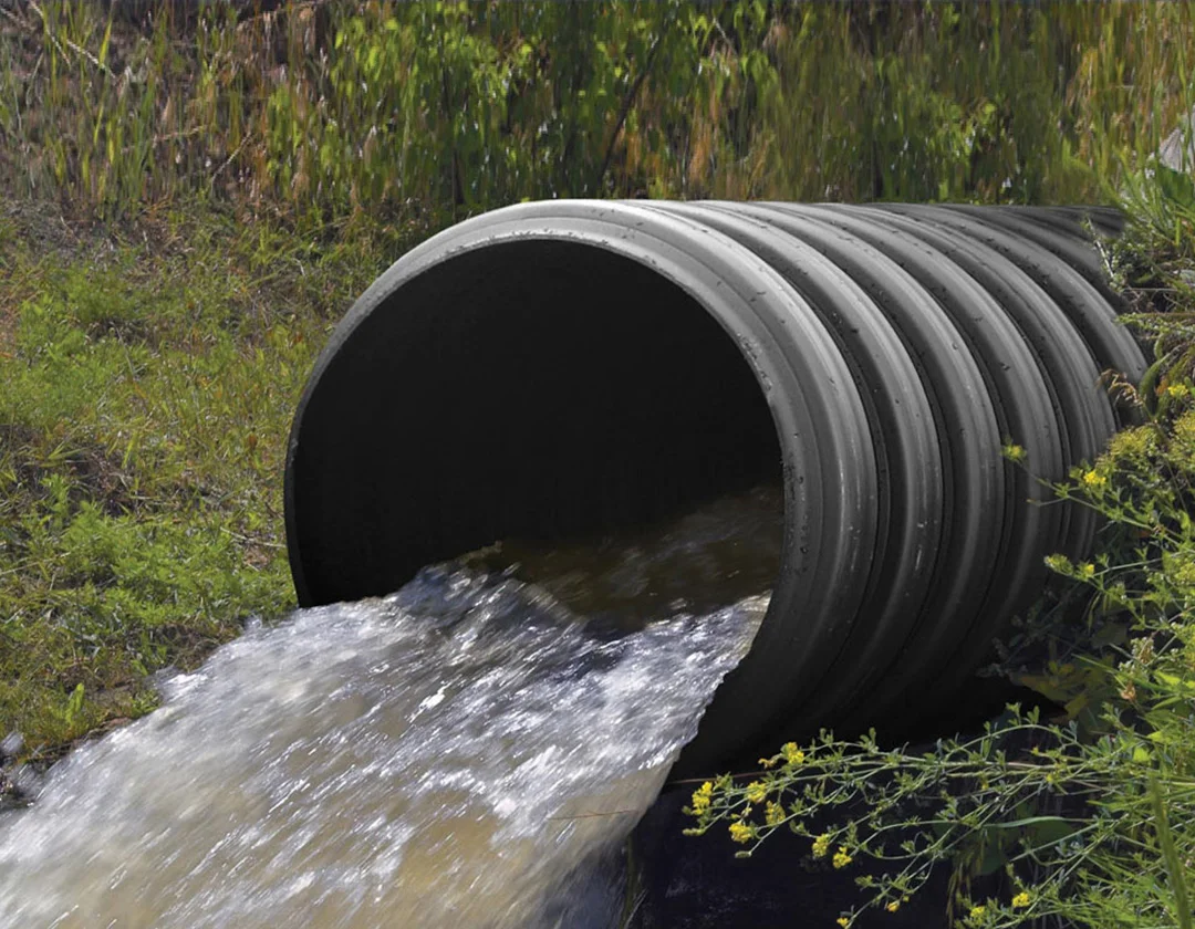

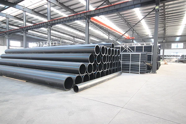

SIFFO offers HDPE (high-density polyethylene) pressure pipes with nominal diameters ranging from 4 to 36 inches, featuring an outside diameter (OD) that complies with the DIPS/DIOD (Ductile Iron Pipe Size/Ductile Iron Outside Diameter) standard. These pipes are specifically designed for municipal water main networks, the rehabilitation of existing pressure pipelines, and integration with established ductile iron piping systems. Manufactured using PE100, PE4710, or PE100-RC grade HDPE resin, the products meet the ANSI/AWWA C906 standard. They serve as an ideal solution for municipal water supply, raw water transmission, reclaimed water systems, and industrial pressure piping applications.
▎Product Specifications
Product | Solid-wall DIPS HDPE pressure pipe |
Nominal size range | 4–36 in. DIPS |
Actual outside-diameter range | 4.800–38.300 in. (121.92–972.82 mm) |
Waterworks standard | ANSI/AWWA C906-21 for documented PE4710 configurations |
ASTM pipe specification | ASTM F714 for applicable DIPS configurations |
Material options | PE4710, PE100 and PE100-RC, according to project requirements |
Straight lengths | 5.8 m or 11.8–12 m, commonly selected for 20 ft or 40 ft container planning |
Coils | 6 in. nominal DIPS and smaller on request |
Joining | Butt fusion, compatible electrofusion fittings, or approved mechanical and flanged transitions |
Pressure options | DR 7; DR 9; DR 11; DR 13.5; DR 17; DR 19; DR 21; DR 26; DR 32.5 |
▎What Is ANSI/AWWA C906?
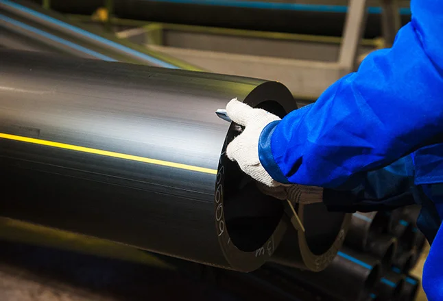
ANSI/AWWA C906 is an American Water Works Association standard for polyethylene pressure pipe and fittings used in waterworks. The C906-21 edition covers nominal sizes from 4 through 65 in. and specifies PE4710 material. It sets requirements for materials, dimensions, testing and marking. SIFFO’s supply range for this DIPS product is 4–36 in. nominal.
▎Why Adopt the Ductile Iron Pipe Size (DIPS) Standard?
HDPE piping does not have an "exclusive" outside diameter (OD) series of its own. In the North American market, it utilizes three established OD systems: the Iron Pipe Size (IPS) used for steel pipes, the Ductile Iron Pipe Size (DIPS) used for ductile iron pipes, and the metric ISO series. The adoption of the DIPS standard is an engineering decision based on compatibility with existing pipeline networks, rather than a requirement dictated by the material itself.
First, it enables direct, size-for-size replacement within ductile iron pipe networks. DIPS outside diameters are precisely—not just approximately—equal to the ODs of AWWA-standard ductile iron pipes. For instance, a 24-inch ductile iron pipe has an OD of 25.800 inches; an HDPE pipe of the same DIPS specification also has an OD of 25.800 inches. This means that when replacing sections of existing cast or ductile iron pipelines, HDPE pipes can be connected directly to existing mechanical joints, valves, fire hydrant branches, and other fittings designed for ductile iron ODs, eliminating the need to redesign connection nodes when switching to HDPE.
Second, it reduces connection costs during pipeline network upgrades. Municipal networks contain a vast number of valves, fire hydrants, tees, and mechanical joints manufactured to DIPS specifications. If HDPE pipes were to use the IPS standard, there would be a significant discrepancy compared to DIPS for the same nominal size (a difference of approximately 58 mm for a 36-inch pipe). Connecting them would require additional adapters or specialized flanges, which increases the variety of materials needed, the risk of leaks, and the time required for installation. By aligning with the DIPS standard, HDPE pipes eliminate the need for such adapters, allowing the inherent advantages of HDPE—corrosion resistance, flexibility, and leak-free heat-fused joints—to be integrated directly into existing ductile iron networks without compromising connection compatibility.
Third, it preserves the intrinsic benefits of HDPE while ensuring the engineering predictability associated with ductile iron systems. Adopting the DIPS specification does not alter the material behavior of HDPE: the pipes still utilize heat-fusion as the primary joining method, retain their flexibility and seismic resistance, and remain immune to corrosion. What it changes is the "standard system to which the pipe's outer diameter aligns." For water treatment plants and municipal pipe networks already in operation, this means that HDPE can be used to address issues such as corrosion, joint leakage, and pipe bursts—common problems with ductile iron pipes—without the need to replace an entire array of valves and fittings due to a mismatch in outer diameters.
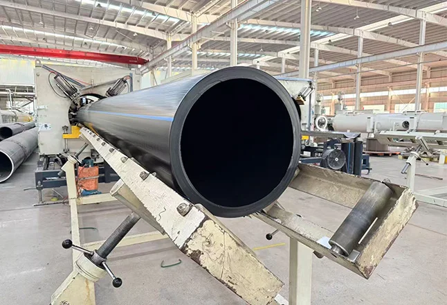
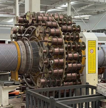
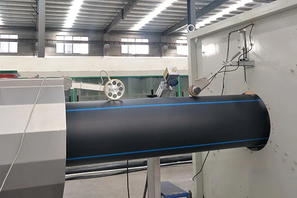
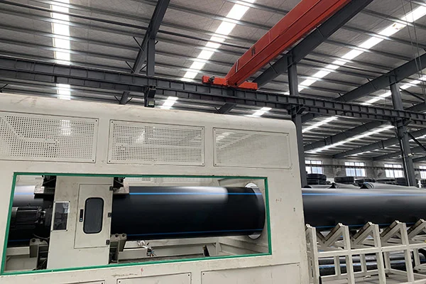
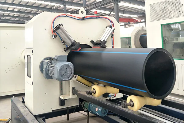
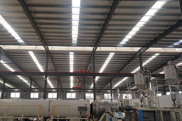
▎SIFFO HDPE Pressure Pipe Production Workshop (Compliant with ANSI/AWWA C906 Standard)
▎Applications of AWWA C906 DIPS HDPE Piping
The scope of AWWA C906 piping is defined by the standard itself: it covers the conveyance of potable water, wastewater, and reclaimed water, and is suitable for buried (trench or trenchless), submerged, and above-ground installations. The DIPS (Ductile Iron Pipe Size) specification further narrows the focus to projects that interface with existing cast iron or ductile iron (DI) pipe networks:
1. Municipal Potable Water Transmission/Distribution Mains and Replacement Segments.
In the renovation of aging cast iron pipe networks, DIPS HDPE can directly replace severely corroded ductile iron sections. It integrates seamlessly with existing ductile iron valves, fire hydrants, and mechanical fittings, eliminating the need for extensive replacement of connection components.
2. Wastewater Pressure Mains and Reclaimed Water Pipelines.
The C906 standard explicitly covers wastewater and reclaimed water applications. HDPE butt-fusion joints ensure leak-free connections, while the DIPS outside diameter (OD) ensures compatibility when connecting new pressure mains to existing ductile iron fittings.
3. Trenchless Rehabilitation and Replacement.
This includes horizontal directional drilling (HDD), pipe bursting, and sliplining. The flexibility and fusion-weldability of HDPE make it ideal for long-distance, continuous installations. The DIPS OD is particularly advantageous for pipe bursting, as it aligns with the dimensions of the existing ductile iron pipe, simplifying the selection of expansion heads and the reuse of existing connection nodes.
4. Industrial and Mining Water Supply and Drainage.
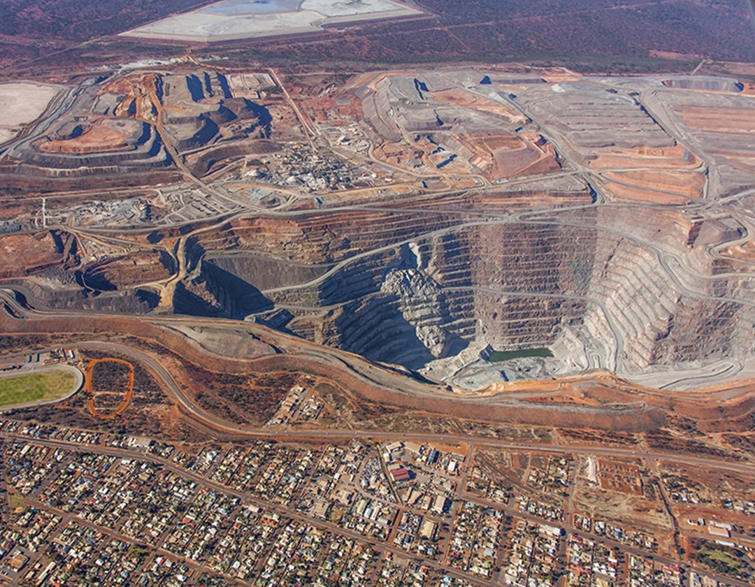
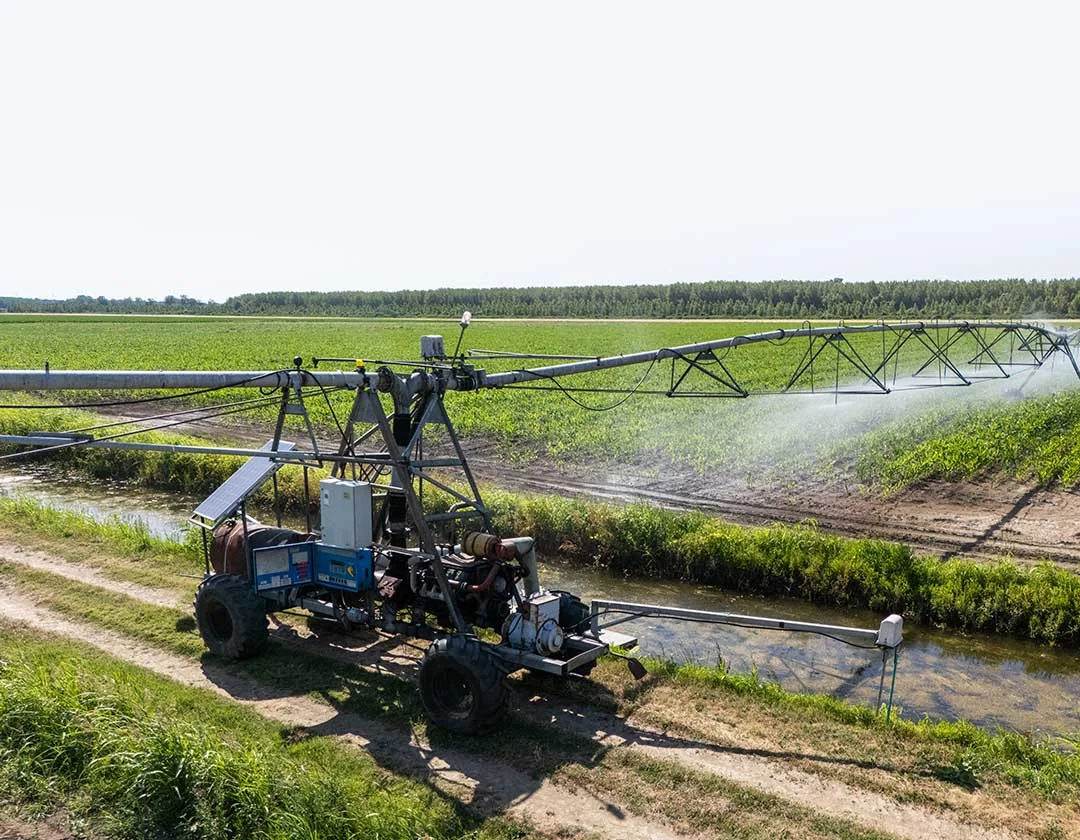
Municipal and industrial water transmission systems represent well-established applications for C906 HDPE piping, spanning sectors such as mining, irrigation, process water supply, and circulating water systems. PE100-RC (Resistant to Crack) variants are well-suited for industrial environments characterized by harsh backfill conditions, point loading, or requirements for superior resistance to slow crack growth.
PIPE | AVG O.D. | MIN. T. | AVG I.D. | WGT | MIN. T. | AVG I.D. | WGT | MIN. T. | AVG I.D. | WGT |
DR 7 (335 psi) | DR 9 (250 psi) | DR 11 (200 psi) | ||||||||
4 | 4.800 | 0.686 | 3.346 | 3.87 | 0.533 | 3.670 | 3.13 | 0.436 | 3.876 | 2.62 |
6 | 6.900 | 0.986 | 4.868 | 7.99 | 0.767 | 5.274 | 6.46 | 0.627 | 5.571 | 5.41 |
8 | 9.050 | 1.293 | 6.309 | 13.75 | 1.006 | 6.917 | 11.12 | 0.823 | 7.305 | 9.32 |
10 | 11.100 | 1.586 | 7.738 | 20.68 | 1.233 | 8.486 | 16.72 | 1.009 | 8.961 | 14.01 |
12 | 13.200 | 1.886 | 9.202 | 29.25 | 1.467 | 10.090 | 23.65 | 1.200 | 10.656 | 19.82 |
14 | 15.300 | 2.186 | 10.666 | 39.29 | 1.700 | 11.696 | 31.77 | 1.391 | 12.351 | 26.63 |
16 | 17.400 | 2.486 | 12.130 | 50.82 | 1.933 | 13.302 | 41.08 | 1.582 | 14.046 | 34.44 |
18 | 19.500 | 2.786 | 13.594 | 63.82 | 2.167 | 14.906 | 51.61 | 1.773 | 15.741 | 43.25 |
20 | 21.600 | 3.086 | 15.058 | 78.31 | 2.400 | 16.512 | 63.32 | 1.964 | 17.436 | 53.07 |
24 | 25.800 | N/A | N/A | N/A | 2.867 | 19.722 | 90.35 | 2.345 | 20.829 | 75.69 |
30 | 32.000 | N/A | N/A | N/A | N/A | N/A | N/A | 2.909 | 25.833 | 116.46 |
36 | 38.300 | N/A | N/A | N/A | N/A | N/A | N/A | 3.482 | 30.918 | 166.84 |
PIPE | AVG O.D. | MIN. T. | AVG I.D. | WGT | MIN. T. | AVG I.D. | WGT | MIN. T. | AVG I.D. | WGT |
DR 13.5 (160 psi) | DR 17 (125 psi) | DR 19 (111 psi) | ||||||||
4 | 4.800 | 0.356 | 4.045 | 2.18 | 0.282 | 4.202 | 1.76 | 0.253 | 4.264 | 1.59 |
6 | 6.900 | 0.511 | 5.817 | 4.50 | 0.406 | 6.039 | 3.64 | 0.363 | 6.130 | 3.27 |
8 | 9.050 | 0.670 | 7.630 | 7.74 | 0.532 | 7.922 | 6.25 | 0.476 | 8.041 | 5.63 |
10 | 11.100 | 0.822 | 9.375 | 11.64 | 0.653 | 9.761 | 9.41 | 0.584 | 9.862 | 8.47 |
12 | 13.200 | 0.978 | 11.127 | 16.47 | 0.776 | 11.555 | 13.30 | 0.695 | 11.727 | 11.99 |
14 | 15.300 | 1.133 | 12.898 | 22.12 | 0.900 | 13.392 | 17.88 | 0.805 | 13.593 | 16.10 |
16 | 17.400 | 1.289 | 14.667 | 28.61 | 1.024 | 15.229 | 23.13 | 0.916 | 15.458 | 20.84 |
18 | 19.500 | 1.444 | 16.439 | 35.92 | 1.147 | 17.068 | 29.04 | 1.026 | 17.325 | 26.15 |
20 | 21.600 | 1.600 | 18.208 | 44.09 | 1.271 | 18.905 | 35.64 | 1.137 | 19.190 | 32.10 |
24 | 25.800 | 1.911 | 21.749 | 62.90 | 1.518 | 22.582 | 50.84 | 1.358 | 22.921 | 45.80 |
30 | 32.000 | 2.370 | 26.976 | 96.76 | 1.882 | 28.123 | 78.18 | 1.684 | 28.430 | 70.45 |
36 | 38.300 | 2.837 | 32.286 | 138.62 | 2.253 | 33.524 | 112.02 | 2.016 | 34.026 | 100.94 |
42 | 44.500 | N/A | N/A | N/A | 2.618 | 38.950 | 151.24 | 2.342 | 39.535 | 136.24 |
48 | 50.800 | N/A | N/A | N/A | 2.988 | 44.465 | 197.05 | 2.674 | 45.131 | 177.57 |
PIPE | AVG O.D. | MIN. T. | AVG I.D. | WGT | MIN. T. | AVG I.D. | WGT | MIN. T. | AVG I.D. | WGT |
DR 21 (100 psi) | DR 26 (80 psi) | DR 32.5 (63 psi) | ||||||||
4 | 4.800 | 0.229 | 4.315 | 1.44 | 0.185 | 4.408 | 1.18 | 0.148 | 4.486 | 0.95 |
6 | 6.900 | 0.329 | 6.203 | 2.98 | 0.265 | 6.338 | 2.43 | 0.212 | 6.451 | 1.96 |
8 | 9.050 | 0.431 | 8.136 | 5.13 | 0.348 | 8.312 | 4.18 | 0.278 | 8.461 | 3.37 |
10 | 11.100 | 0.529 | 9.979 | 7.72 | 0.427 | 10.195 | 6.29 | 0.342 | 10.375 | 5.08 |
12 | 13.200 | 0.629 | 11.867 | 10.91 | 0.508 | 12.123 | 8.91 | 0.406 | 12.339 | 7.18 |
14 | 15.300 | 0.729 | 13.755 | 14.66 | 0.588 | 14.053 | 11.95 | 0.471 | 14.301 | 9.65 |
16 | 17.400 | 0.829 | 15.643 | 18.96 | 0.669 | 15.982 | 15.46 | 0.535 | 16.429 | 12.49 |
18 | 19.500 | 0.929 | 17.531 | 23.81 | 0.750 | 17.910 | 19.95 | 0.600 | 18.228 | 15.67 |
20 | 21.600 | 1.029 | 19.419 | 29.22 | 0.831 | 19.838 | 23.84 | 0.665 | 20.190 | 19.24 |
24 | 25.800 | 1.229 | 23.195 | 41.68 | 0.992 | 23.697 | 33.99 | 0.794 | 24.117 | 27.44 |
30 | 32.000 | 1.524 | 28.769 | 64.11 | 1.231 | 23.390 | 52.31 | 0.985 | 29.912 | 42.22 |
36 | 38.300 | 1.824 | 34.433 | 91.84 | 1.473 | 35.177 | 74.92 | 1.178 | 35.873 | 60.43 |
42 | 44.500 | 2.119 | 40.008 | 123.96 | 1.712 | 40.871 | 101.17 | 1.369 | 41.480 | 81.59 |
48 | 50.800 | 2.419 | 45.672 | 161.55 | 1.954 | 46.658 | 131.83 | 1.563 | 47.486 | 106.34 |