

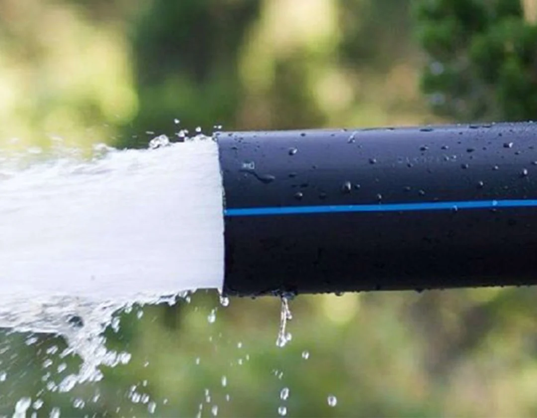


PVC Pipeline Construction and Installation
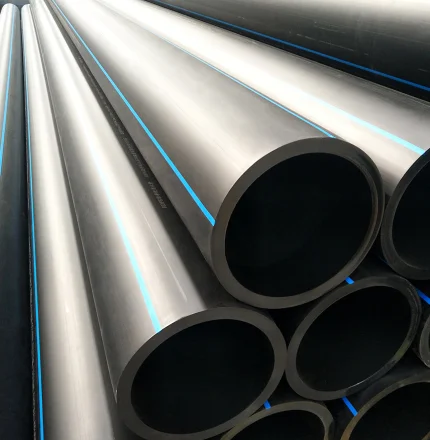
1. PVC piping installation works encompass the installation of straight PVC pipes, elbows, tees, crosses, and associated fittings.
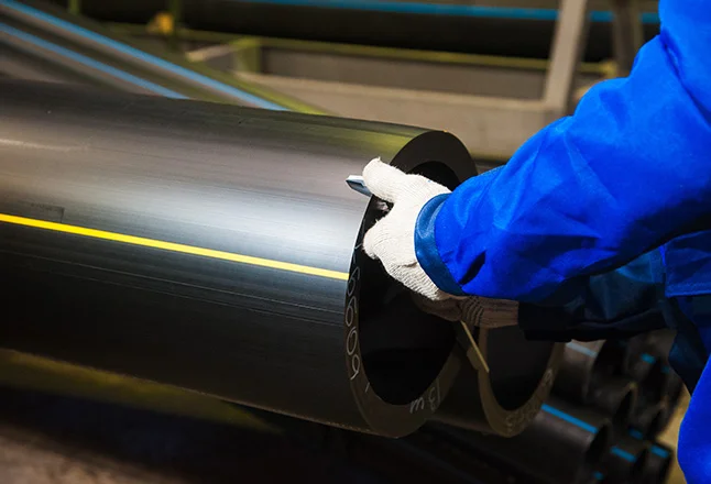
2. Material control: Prior to installation, verify that all documentation for the pipes and fittings is complete; PVC materials must be accompanied by factory certificates of conformity and relevant quality inspection records. The quality of the piping materials must meet the applicable national standards.
3. PVC Pipe Installation
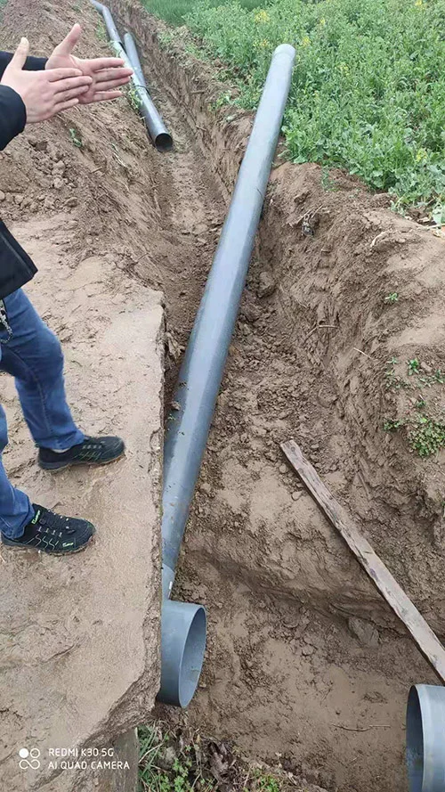
(1) Pipe laying shall commence only after the trench bottom elevation and the quality of the pipe trench foundation have passed inspection.
(2) The pipe foundation material shall be free of debris such as grass roots. Where the foundation consists of rock, a sand bedding layer with a thickness of at least 15 cm shall be laid.
(3) Trench excavation and backfilling shall be carried out in accordance with the 《Technical Specification for Buried Polyethylene Water Supply Pipeline Engineering》 (CJJ91-2004) and other relevant standards.
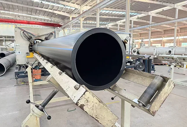
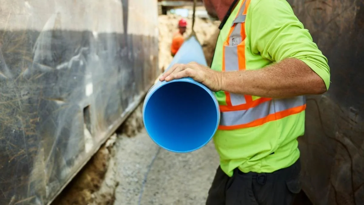
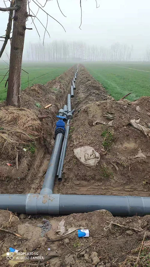
(4) Reliable lifting equipment shall be used for hoisting and lowering large-diameter pipes into the trench. When handling PVC pipes, soft lifting straps or devices that do not damage the pipe shall be used. Individual pipes and pipe sections shall be lowered steadily into the trench, avoiding any impact with the trench walls or bottom.
(5) Each pipe must be carefully aligned at the center; the slope of secured pipes and pipe sections shall be verified using measuring tools, ensuring close contact between the pipe bottom and the foundation.
(6) Pipe joints shall be connected only after the PVC pipes have been aligned and the slope verified to meet design requirements. Pipe welding shall be the responsibility of the supplier, who shall also provide the necessary welding equipment.
(7) Whenever installation or laying work is interrupted, open pipe ends shall be sealed with end caps or cover plates.
4. Quality Inspection
(1) Materials comply with the requirements of the drawings and relevant specifications.
(2) Pipeline installation and laying comply with the requirements of the 《Code for Construction and Acceptance of Water Supply and Drainage Pipeline Engineering》.
(3) Conduct a thorough visual inspection of pipelines, expansion joints, connection points, and other ancillary structures; also, verify against the design that water can drain freely from all points along the pipeline.
(4) Pipelines shall be flushed with water prior to acceptance.
5. Precautions
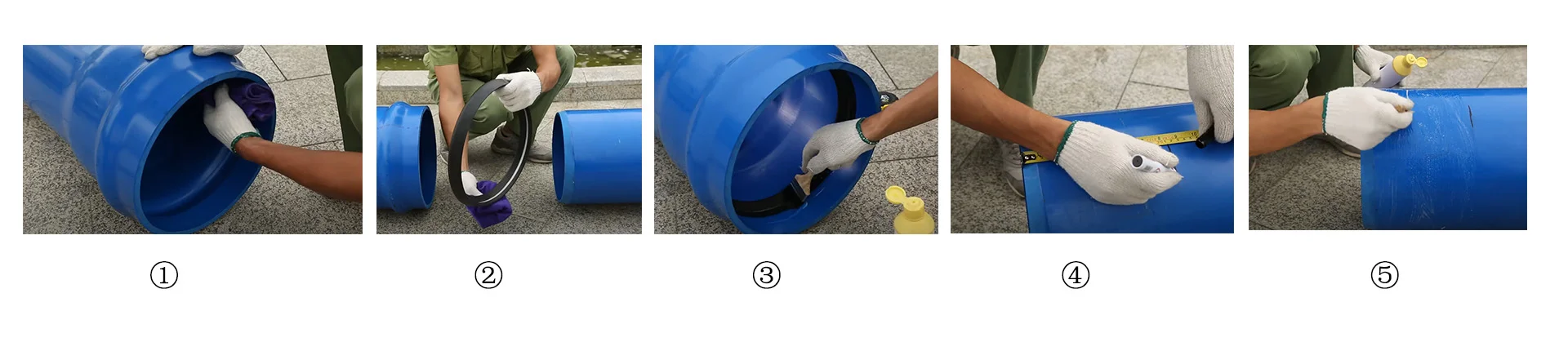
(1) When installing pipes with spigot-and-socket joints, the spigot end (smaller end) should point in the direction of the water flow.
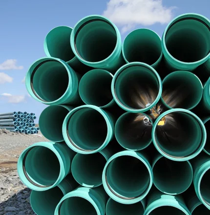
(2) For butt-joint installations of pipes with the same diameter, the coupling sleeve must be compatible and the joint fit tight; the pipes must be aligned on a straight axis, and the overlap between the sleeve and the main pipe must be at least 9 cm.
(3) In areas with complex terrain or significant elevation differences, in addition to selecting pipe materials based on design pressure, the installation must include thrust blocks and additional air inlet/exhaust valves.
(4) Pipeline installation should ideally avoid the hottest summer months and the coldest winter months. PVC pipes exhibit significant changes in linear dimensions due to temperature fluctuations; therefore, installation must be carried out strictly in accordance with relevant technical specifications.
6. Hydrostatic Closure Test (Water-Tightness Test)
The following conditions must be met prior to the hydrostatic closure test:
All open ends of the pipeline section to be tested must be sealed, and there shall be no leakage.
Sluice valves shall not be used as end caps for the test section, and the section shall not contain accessories such as fire hydrants, water hammer arresters, or safety valves.
Debris within the pipeline must be cleared prior to the hydrostatic pressure test.
Fixed supports for exposed (non-buried) piping must be installed in compliance with design requirements.
Pipeline auxiliary equipment must be securely fastened and anchored in accordance with requirements.
The concrete for pipe fitting thrust blocks and anchoring facilities must have reached the design strength.
For pipe fittings lacking thrust blocks or anchoring facilities, reinforcement measures must be implemented and verified.
Before the test, a visual inspection of the joints and pipe bodies within the test section must be conducted; the section is deemed acceptable if there is no leakage or significant seepage.
The hydrostatic closure test shall be performed before backfilling the pipeline joints. The test water level shall be 2 meters above the crown of the upstream pipe within the test section. After soaking the pipe for 1 to 2 days, the seepage volume shall be measured. The measurement duration shall be no less than 30 minutes, and accurate records of the test must be maintained.
Seepage measurement shall be conducted in accordance with relevant standards. Timing for seepage observation begins when the test head is reached and continues until the observation concludes (duration ≥ 30 minutes). During observation, water must be continuously added to the test section to maintain a constant test head. The volume of added water shall be measured using a graduated cylinder.
Q = 1440 × W / (T × L)
Where: Q = Measured seepage volume (m³/24h·km)
W = Volume of added water (L)
T = Observation time for seepage measurement (min)
L = Length of the test pipeline section (m)
Pipeline Backfilling
During pipeline construction, backfilling proceeds alongside the laying of the pipe body; however, backfilling at pipe joints must be deferred until the hydrostatic test (water-tightness test) has been successfully completed.
1. The following conditions must be met prior to backfilling:
(1) The strength of cast-in-place concrete foundations, joint mortar bands, or cement mortar at joints of assembled precast components must be at least 5.0 N/mm².
(2) The fill material within the zone extending from the trench bottom to 500 mm above the pipe crown must be free of organic matter, frozen soil, and hard debris (such as bricks or stones) larger than 50 mm. During backfilling, material must be deposited symmetrically from both sides of the trench; dumping large quantities at a single point is prohibited.
(3) For circular or rectangular manholes, the cement mortar strength of masonry structures must meet design specifications, and precast cover slabs must be properly installed.
2. Compaction of the trench backfill must comply with the following requirements:
(1) For trenches located within the roadbed, the compaction degree must be at least 87% for the zone within 250 mm above the pipe crown and at least 90% for other areas. Backfilling operations may only commence after the pipeline has passed the hydrostatic test.
(2) Manual compaction is required for the zone within 500 mm above the pipe crown, while mechanical compaction is used for the zone more than 500 mm above the pipe crown.
3. Construction Process
(1) Transport backfill material into the trench based on the required quantity for each loose-fill layer; do not stockpile materials within the zone that would interfere with compaction operations.
(2) Backfill material for the areas on both sides of the pipe and up to 500 mm above the pipe crown must be deposited symmetrically from both sides of the trench; it must not be dumped directly onto the pipe. For other areas, backfill material should be distributed evenly into the trench rather than pushed in as a concentrated mass.
(3) Backfill soil must be spread in layers. The thickness of each layer should be determined based on soil type, compaction requirements, and equipment performance.
(4) For mechanical rolling, the loose-fill layer thickness should be 120–150 mm; for areas inaccessible to machinery, manual tamping is required, with a loose-fill thickness not exceeding 150 mm. After spreading, the surface should be leveled with an iron rake.
(5) To prevent displacement of the pipe centerline or damage to the pipe during backfilling, soil on both sides of the pipe must first be filled and tamped manually; this process must proceed simultaneously from both sides. Mechanical compaction may only be used once the fill reaches a level more than 0.5 m above the pipe crown, ensuring no damage occurs to the pipe.
(6) After each layer of backfill is tamped, ring-cutter sampling must be performed in accordance with specifications to measure the dry soil density; the next layer may only be spread after requirements are met.
(7) Surface leveling: Upon completion of all backfilling, the surface should be leveled using a guide line. Areas exceeding the target elevation must be trimmed down promptly, while areas below the standard elevation must be filled and tamped. Areas alongside the pipe (pipe haunches) and within 50 cm above the pipe crown should be compacted using a frog rammer, with a loose-fill layer thickness of 20–30 cm. Areas more than 50 cm above the pipe crown should be compacted using a road roller, with a loose-fill layer thickness of 30–50 cm.
(8) Backfill soil must be free of debris such as bricks and humus. Moisture content should be close to the optimum level and not excessive; if the moisture content is too high, the soil should be air-dried or mixed with lime before backfilling.
(9) During compaction, work must proceed symmetrically on both sides of the pipe to avoid displacing or damaging the pipe. (10) When backfilling and compacting in sections, the joints between adjacent sections shall be stepped, and no areas shall be missed during compaction.
(11) When backfilling around inspection wells, the backfill material shall be placed simultaneously on all sides. Where feasible, new technologies, methods, and materials should be adopted to minimize settlement around inspection wells during pipeline construction.